
SIPBS Modelling
Findings from POE indicated that the building did not perform as expected in terms of energy consumption and occupants comfort. Furthermore, it was established through interviews with the mechanical and electrical consultants and the estate services that there were some issues regarding operation of the building, which potentially, is one of the factors responsible for the building’s underperformance.
From these POE findings a number of scenario questions were then considered:
- What if there was an agreement for seasonal commissioning?
- What if there was contractual agreement for an extended after care, so that operation of plants and HVAC systems goes on smoothly, while our client is given an extensive training?
- What if the client was made to understand the system that was being designed, at the beginning, from the design stage; in a virtual way?
- What if the client was able to model the building [in dynamic simulation environment], its systems and controls as they were intended to be built and then use this as a living model that grows and changes as the process progressed? Thereby enabling the client to compare current performance to some base case (benchmark). One example being a model of the state of the building, systems and controls at the end of commissioning.
These scenario questions prompted considerations of the viability of dynamic building simulation as a tool for supporting early design decisions, commissioning, fault identification and performance monitoring. Moreover these questions also prompted consideration of the building delivery processes, vis-a-vis RIBA and Soft Landings.
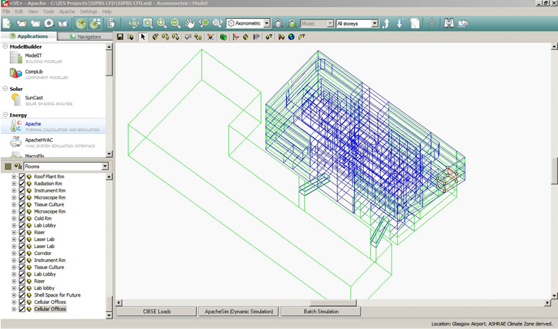
Dynamic simulation using the IESVE software
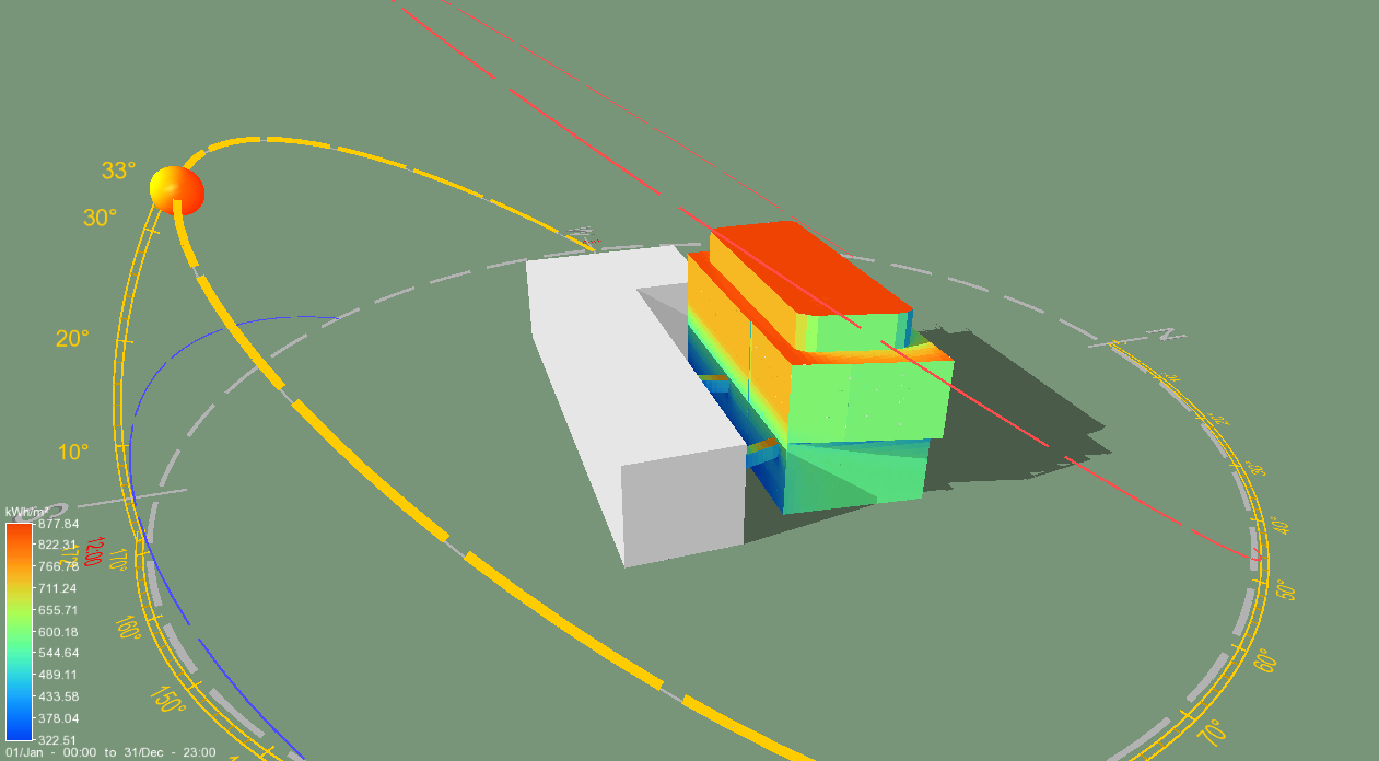
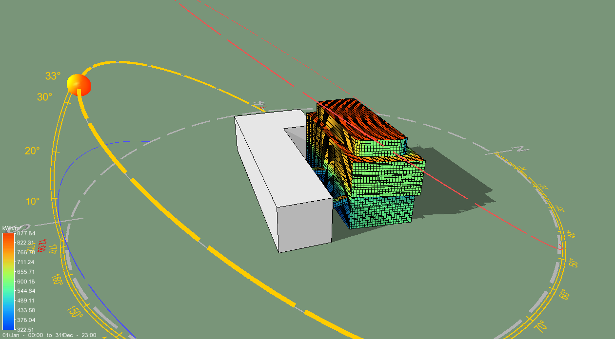
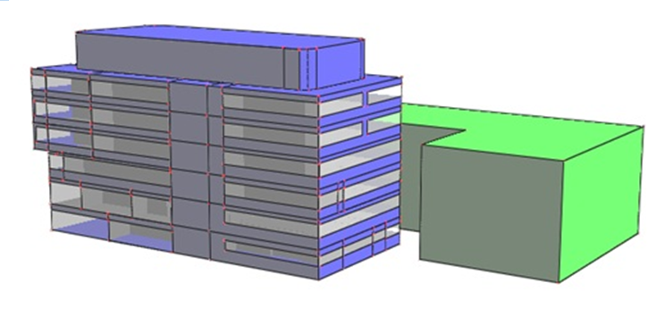
IESVE software was used for modelling the SIPBS building and to account for overall energy consumption of the whole building. The model included all the zones and HVAC plant and systems as they exist in reality. The NCM (2010) building templates were used for material and scheduling.
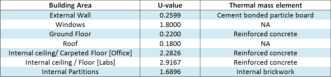
Building Materials and their properties used for simulation are shown in the table below.
Thermal Templates
Building thermal templates were defined separately for an office zone, teaching lab and specialist’s lab, each one with different HVAC systems and set-points as per the design briefs.
- The Model’s office zone HVAC system consists of two systems: the main HVAC system (chilled beams with centralised ventilation, with primary and secondary air tempering) and an auxiliary system (consisting of a radiant panel for when the chilled beam works in heating mode during the winter).
- The Model’s laboratories HVAC systems consist of two cooperative systems: primary system acting as a VAV central unit and an auxiliary air conditioning system acting as fan-coils.
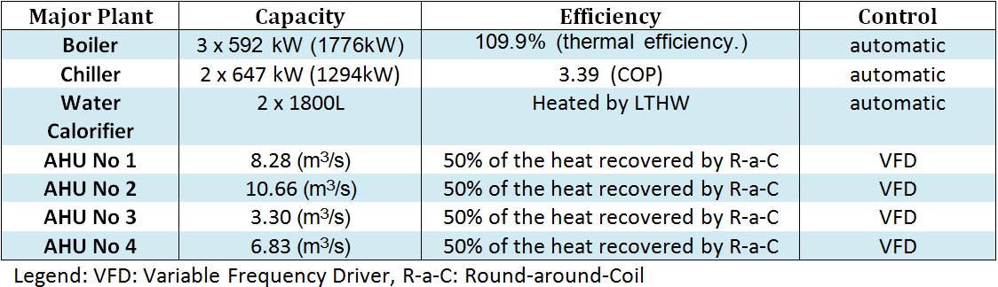
The paramaters of major plant are shown in the table below.
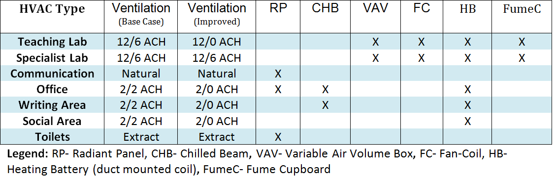
The paramaters of HVAC systems are shown in the table below.
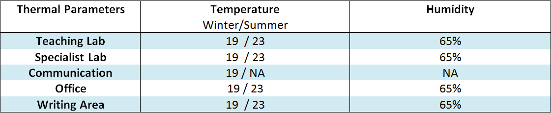
The comfort targets applied are shown in the table below.
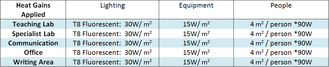
The internal gains applied are shown in the table below.